Trailer Connector Wiring Diagram 7Way Wiring Diagram
Trailer wiring can be one of the most intimidating components of your towing setup, but it doesn't have to be. Most of us aren't electricians, but that doesn.
Seven Pin Trailer Connector Wiring Diagram
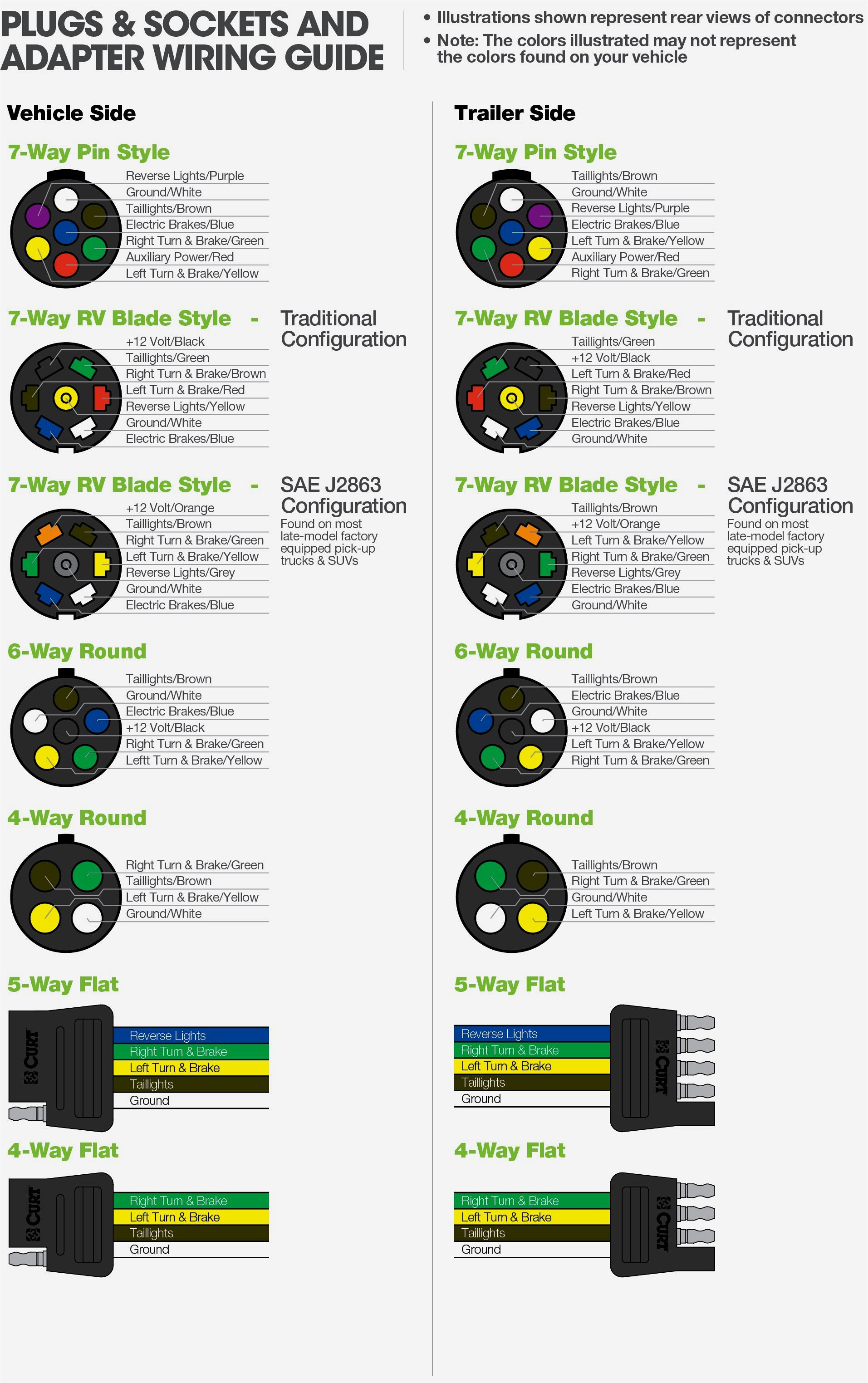
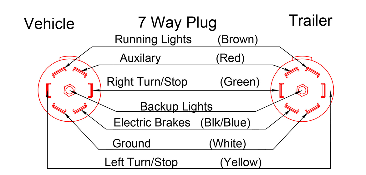
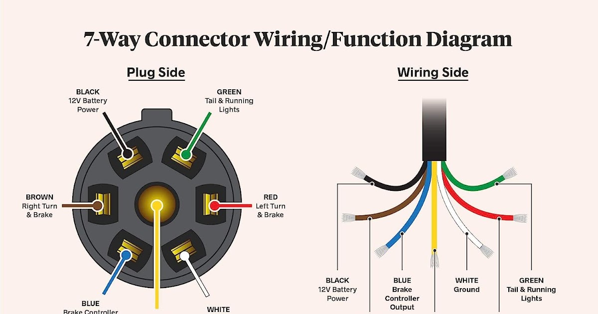
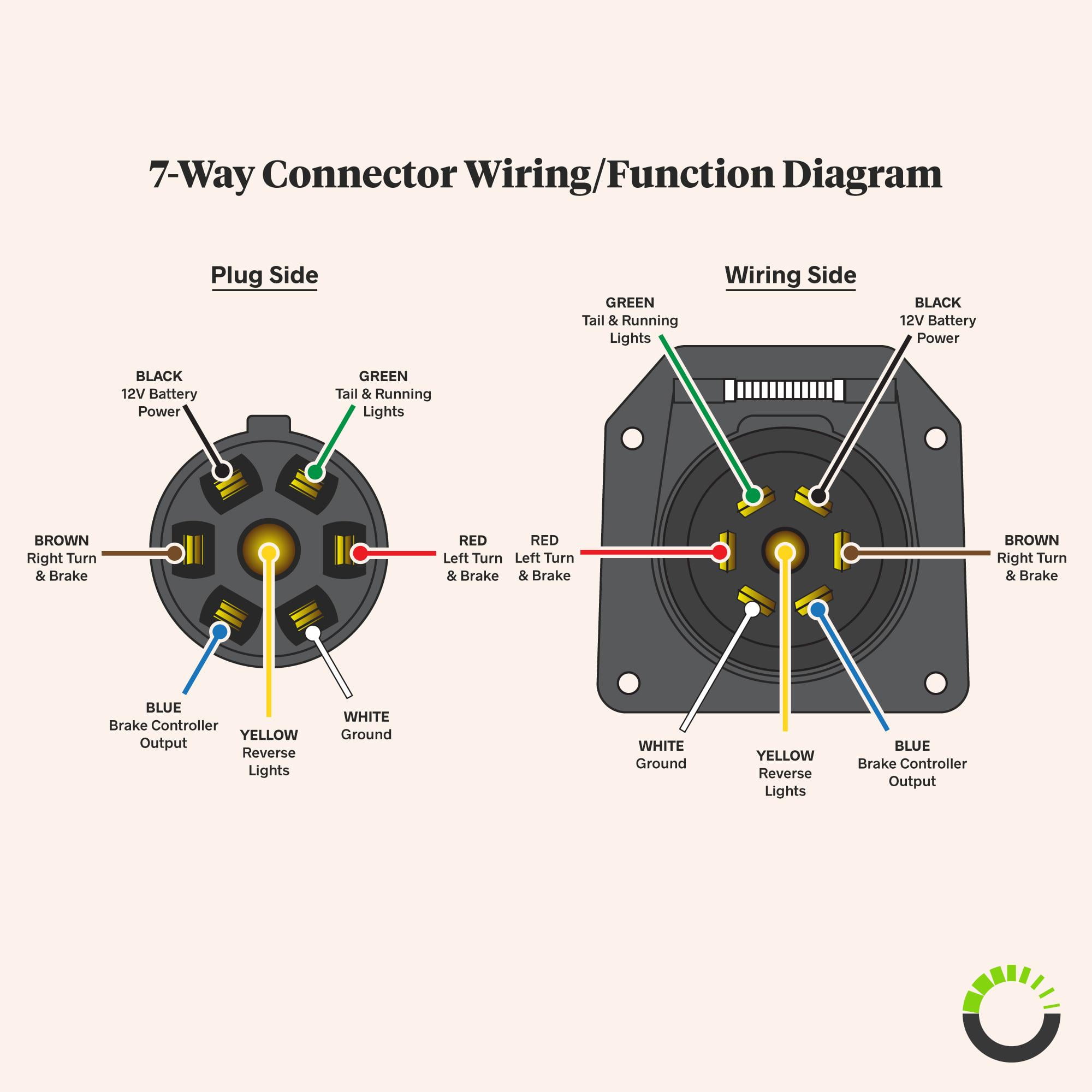
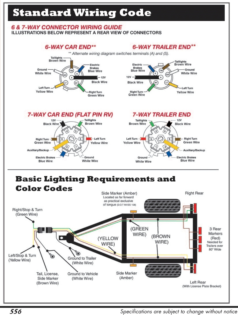
7 Way Plug Wiring Diagram Standard Wiring* Post Purpose Wire Color TM Park Light Green (+) Battery Feed Black RT Right Turn/Brake Light Brown LT Left Turn/Brake Light Red S Trailer Electric Brakes Blue GD Ground White A Accessory Yellow This is the most common (Standard) wiring scheme for RV Plugs and the one used by major auto manufacturers today.
Sienna Wiring 7 Pin Semi Trailer Connector Wiring Diagram Example Pdf Converter

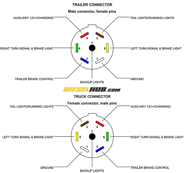
The seven pins in a trailer plug are labeled with numbers or letters for easy identification. Here is a breakdown of the pin configuration: Pin 1: This pin is used for the left turn signal or indicator lights. It connects to the corresponding wire on the towing vehicle. Pin 2: The second pin is for the reverse lights.
Wiring A 7 Way Trailer Connector Diagram

Step 3: Test Connections. Before sealing everything, conduct a thorough test. Connect the trailer plug to the vehicle's socket and check if all lights and functions are working correctly. Test the tail lights, turn signals, brake lights, and any other accessories connected to the plug.
Wiring Diagram For Trailer Plug 7 Pin
The 7 pin trailer plug is the most common wiring connection used for towing a trailer. This plug provides power for the trailer's lights, brakes, and other electrical components, making it essential to understand how to properly wire it. This article will serve as a comprehensive guide to the 7 pin trailer plug wiring diagram. We will cover.
Trailer Wire Diagram 7 Pin
The diagram for a 7 way trailer plug shows how these pins are arranged and what they are used for: Pin 1: Ground - This pin is used to provide a ground connection for the trailer. Pin 2: Electric Brakes - This pin is used to supply power to the trailer's electric brakes. Pin 3: Tail Lights - This pin is used to provide power for the.
7 Pin Trailer Connector Wiring

This diagram provides a clear understanding of how the seven pins on the plug are connected to different electrical components of the trailer. The 7-pin plug wiring diagram for trailers typically includes the following pins: Pin 1: Left Turn Signal. Pin 2: Reverse Light.
7 Way Semi Trailer Plug Wiring Diagram With Abs Paintal

Step 3: Connect the Wires. Connect each wire to the corresponding pin on the seven way trailer plug. Use wire connectors or soldering to ensure a secure and lasting connection. It's important to follow the wiring diagram closely to avoid any mistakes.
7 pin wiring diagram Wiring Diagram

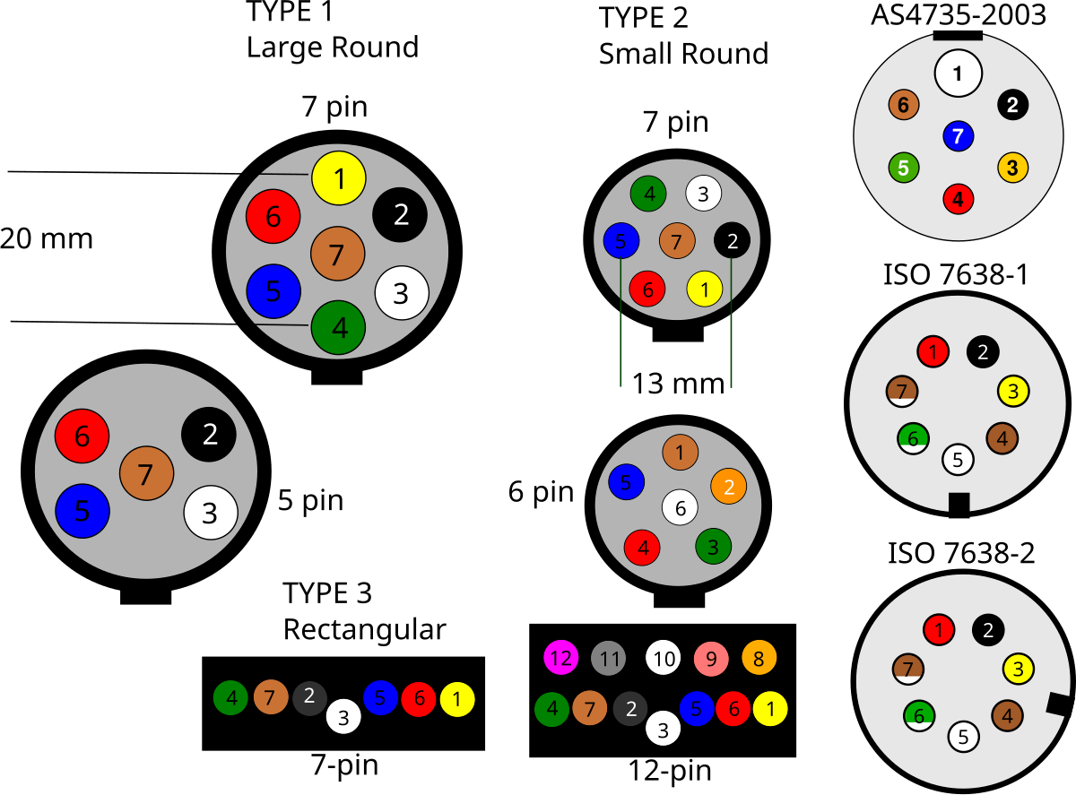
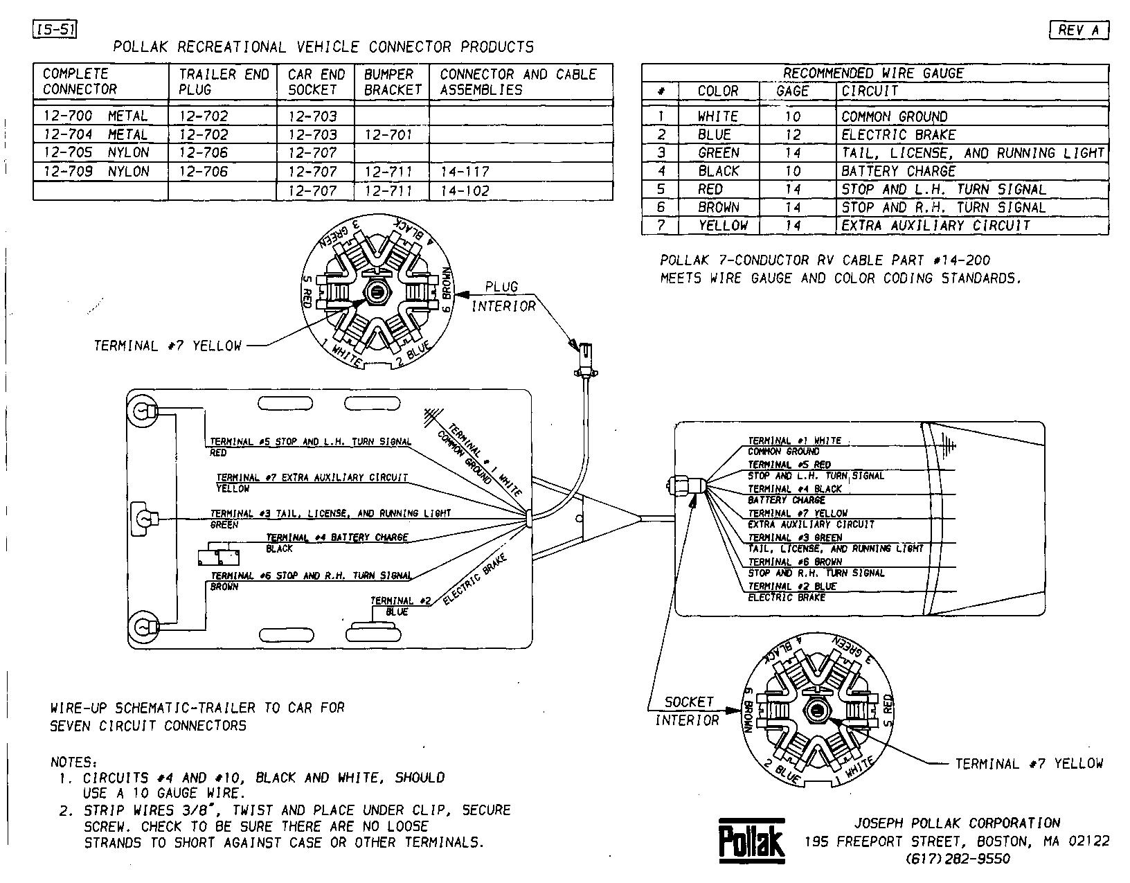
I just purchased a used travel trailer. 7 pin connector on trailer and my F150. When connected only the tail/running lights and trailer brakes work.. Wiring Diagram for 7-Way Round Pin Trailer and Vehicle Side Connectors. I have added a photo detailing the wiring connections for the Pollack Heavy-Duty, 7-Pole, Round Pin conncetor, #PK11700.
Standard 7 Way Trailer Plug Wiring Diagram
Trailer Wiring Connectors. Various connectors are available from four to seven pins that allow for the transfer of power for the lighting as well as auxiliary functions such as an electric trailer brake controller, backup lights, or a 12V power supply for a winch or interior trailer lights. Choose a connector that has the required number of.
Wiring Seven Pin Trailer Plug
In the Trailer Wiring Diagram and Connector Application Chart below, use the first 5 pins, and ignore the rest. If your truck has a built-in 7-pin socket, but you only need 5 of the pins. Use the 7-pin connector anyway (see below), and just leave out the last 2 wires.
7 Way Rv Trailer Connector Wiring Diagram Wiring Diagram Library
The 7-pin trailer plug is the most common type used for connecting trailers to vehicles, providing all the necessary signals for lights, brakes, and other electrical components. In this comprehensive guide, we will walk you through the complete wiring diagram for a 7-pin trailer plug, making installation a breeze.
Wiring Diagram For 7 Pin Trailer Plugin Wiring Diagrams Harley Blog

A 7 pin trailer wiring diagram is a schematic that shows the pinout and function of each wire in a 7-way round trailer connector. The standard 7-pin connector contains the following wires and functions: The diagram uses color coding and labeling to identify the purpose of each pin's wire. It traces the path of the wires from the connector.
How to wire a trailer plug 7 pin (diagrams shown) YouTube
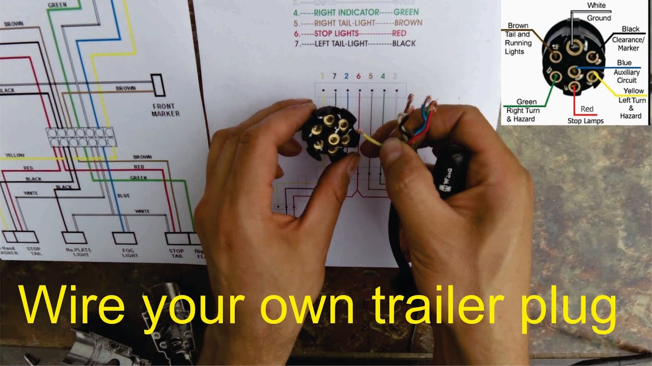
This trailer wiring guide comes complete with a color coded trailer wiring diagram for each plug type, including a 7 pin trailer wiring diagram, this guide walks through various trailer wiring installation solution, including custom wiring, splice-in wiring and replacement wiring. If your vehicle is not equipped with a working trailer wiring harness, there are a number of different solutions.
7 Pin Trailer Connector Diagram Light Switch Wiring Diagram

In order to do that, there must be power to the trailer. A 7-pin plug (sometimes referred to as the "7-way trailer connector") is the connector and heavy-duty wire that brings the necessary power and related functions to the trailer you're towing. The connector is 2″ in diameter and is often found on heavy-duty trailers such as RVs.
7 Pin Trailer Connector Wiring Diagram Cadician's Blog
The wiring diagram for a 7 pin trailer connector is an essential tool for ensuring proper installation of the electrical connections between a tow vehicle and a trailer. The 7 pin trailer connector is commonly used for towing trailers with electric brakes or for powering various accessories on the trailer, such as lights and brake controllers..